How to chose the right sensor or gauge for the application
The terms Quality Control, Process Control and Inspection are banded around regularly but often their relationship is not as clearly understood as they should to make the best choices on both what and how to measure.
Naturally the issue is one of control. Whether this entails an automatic feedback control device or that function is performed by an operator (see “Control Explained”).
Typically a sensor is a device with an electronic output but no display. Our general definition of a gauge is a combination of sensor and display that shows a physical unit (e.g. mm, kg, m/min, kp, PSI, deg.C etc.).
Below are some explanation on how various gauges and sensors measure.
Scanning laser gauges
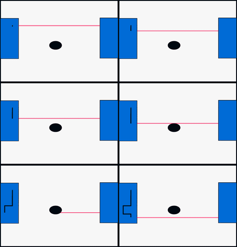
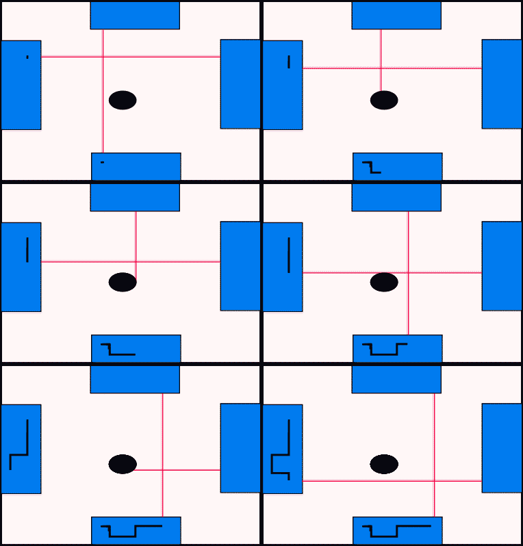
The scanning laser gauge measures by continuously moving a laser beam from top to bottom or left to right and effect-ively measuring the length of the shadow period. This can happen at speeds up to 2400 scans/sec. which means that most product movement does not cause any issues with respect to the measurement accuracy. Even fast vibration is basically
cancelled out over the average of multiple scans.
These gauges can measure in one, two or three axis simultaneously and are mainly used to measure cables, wires, tubes, rods, bars and the like.
Accuracy is very high and they are highly resilient because the laser power is high and as long as it gets a shadow on the receiver end then it will basically produce a valid measurement.
The surface or material is irrelevant and to a limited degree they can be used to detect lumps and neck-downs.
These gauges have a defined “Measuring Field” and the maximum size object is usually the size of the measuring field less 1 mm less the expected movement of the product.
However, depending on the application the product does not have to be entirely in the measuring field.
If used in “Penetration” mode it can be used to measure a shadow entering the measuring field from one or even both directions. This means you can measure thickness over a known roller or the gap between two rollers.
In such applications the position of the gauge relative to the object to be measured becomes important as any movement of the sensor distorts the result.
These gauges can measure in one, two or three axis simultaneously and are mainly used to measure cables, wires, tubes, rods, bars and the like.
Accuracy is very high and they are highly resilient because the laser power is high and as long as it gets a shadow on the receiver end then it will basically produce a valid measurement.
The surface or material is irrelevant and to a limited degree they can be used to detect lumps and neck-
However, depending on the application the product does not have to be entirely in the measuring field.
If used in “Penetration” mode it can be used to measure a shadow entering the measuring field from one or even both directions. This means you can measure thickness over a known roller or the gap between two rollers.
In such applications the position of the gauge relative to the object to be measured becomes important as any movement of the sensor distorts the result.


Laser Triangulation
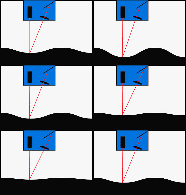
The triangulation laser sensors emit a laser beam onto the surface and use an oblique camera to look at the position of the dot that was created. Based on the
position it will determine the distance of that dot from the face of the sensor. Hence their are often called “Distance Sensors” but they can be used to measure any sort of mechanical dimension as long as the sensor is applied correctly and its output is displayed accordingly.
Two can be mounted opposite each other to directly show thickness irrespective of the position of the product.
They a have a “Range” which indicates the acceptable variation in distance that can be displayed and a “Stand-off Distance” which is typically the distance from the face of the sensor to the centre of the range.
The measurement surface plays a crucial part in this measurement method. If high accuracy is required then a surface with consistent reflectivity should be guaranteed.
Also, because the camera is looking from an oblique angle the orientation of the sensor is critical when sharp steps are to be measured because the edge can shadow the camera and the signal can be lost.
Highly reflective objects can lead to insufficient diffusion with most of the light being deflected or reflected in the wrong direction. Likewise, very black surfaces that absorb a lot of light may require a higher laser intensity and make automatic laser power control a necessity.
However, many sensors can even measure the blackest of black and only struggle with highly porous black material.
Two can be mounted opposite each other to directly show thickness irrespective of the position of the product.
They a have a “Range” which indicates the acceptable variation in distance that can be displayed and a “Stand-
Also, because the camera is looking from an oblique angle the orientation of the sensor is critical when sharp steps are to be measured because the edge can shadow the camera and the signal can be lost.
Highly reflective objects can lead to insufficient diffusion with most of the light being deflected or reflected in the wrong direction. Likewise, very black surfaces that absorb a lot of light may require a higher laser intensity and make automatic laser power control a necessity.
However, many sensors can even measure the blackest of black and only struggle with highly porous black material.
